Operations & Maintenance
Setup, routine operation, maintenance/consumables, safety/SDS, troubleshooting, and FAQs—consolidated from each product page.
Jump to a product
- ASAP V
- D1000 Downdraft Table
- Negative Pressure Room
- QuikTest Bioscreen
- RSN 5000
- SASS 2300
- SASS 3010
- SASS 3100
- SASS 4000
ASAP V
Operational Details
Overview
Each node consists of a central instrument box that houses communication electronics and those sensor modules that need to be centrally located, such as the aerosol biohazard module. Other modules, such as video and sound, may be mounted externally and can be supplied in a cabled format. Research International will work with each customer to provide a customized solution that best meets their requirements.
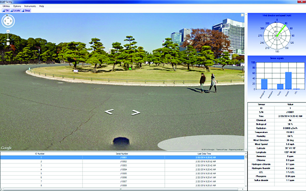
The ASAP V software interface allows easy integration of the diverse modules. It provides immediate visual feedback regarding the status of the individual sensors. By a button click, the user can examine each detector’s output over the past 24 hours. Through pull-down windows, each detector’s performance can be examined or adjusted as appropriate for immediate conditions. A permanent record of each module’s data is stored for archival study.
Biological Agents
A detection module based on Research International’s Tac-7C® biodetector monitors continuously for unusual patterns in ambient aerosol levels. Upon observation of suspicious changes, it automatically initiates wet sample collection. Airborne particles are first collected into a small amount of water or onto a high efficiency filter, and then analyzed using wet immunoassay methods. Both manual test strip and fully automated wet assay methods are available. For higher sensitivity, an aerosol pre-concentrator is also available.
Testing is only performed when a threat is detected, greatly reducing the cost of consumables as compared to other wet bioassay strategies.

Chemical Agents
Airborne chemical agents are detected using an ion mobility spectrometer produced by a major world manufacturer. The module offers fast and reliable detection of a wide range of airborne toxic industrial chemicals and chemical warfare agents. The unit provides continuous real-time operation with a response time of only a few seconds.
Nuclear Materials
Two modules are available based on gamma ray scintillator products. One module is amenable to portal monitoring situations where the presence of radio-isotopes and special nuclear materials are of concern at an entry point to a controlled area. The second module is more suited for area monitoring gamma ray background levels.
The system can be programmed to signal this event to the monitoring PC, and to run a programmed collection protocol using a high-efficiency dry filter system. Research International can provide this functionality based either on the SASS® 3100 or SASS® 4100 dry filter aerosol particle collectors.

Meteorological
This module is based on meteorological systems provided by Coastal Environmental Systems of Seattle, WA. Sensors can be provided for wind speed and direction, relative humidity, temperature, pressure, visibility, and precipitation. Optionally the system can monitor the area with video.
Explosives
The presence of unusual levels of explosive vapors and particulates is determined using a module based on Ion Trap Mobility Spectrometry (ITMS™) technology. Analysis and reporting times are under 10 seconds.
Intrusion Detection
Several intrusion detection technologies are available, based on detection methods ranging from microwave to acoustic. Please let us know the approximate dimensions (height × width × depth) of your monitored surveillance area and the normal operating temperature range, and we will provide one or more recommended solutions.
Thermal Imaging
Body temperature imaging (8 to 14 microns, typ.) is an excellent method for performing covert surveillance or fire detection, among other functions. Microbolometer technologies have now made this a cost-effective technology to incorporate into ASAP V for Critical Infrastructure Protection. Thermal imagers can be installed with arrays ranging up to 96 × 96 in size.
D1000 Downdraft Table
Operational Details
Overview
Manual inspection processes involving the handling and opening of postal materials, shipping boxes, luggage, handbags, and packaged merchandise pose a risk to personnel during the inspection process and to the buildings in which the inspections are being done. If an article contains a biological agent, toxic chemical, or explosive or flammable material, many different types and levels of damage could occur if the material was indiscriminately released or not detected.
The D1000 downdraft table is a patented device1 designed to mitigate many of the life-threatening and/or infrastructure-damaging results of such hidden dangers and is of particular value to private and governmental postal inspection facilities.
Ref. 1: U.S. Patent No. 7,377,952.
Airflow & Filtration
The D1000 table incorporates a perforated metal surface over which suspect articles are opened. Inside the table are powerful brushless motor-powered blowers that pull air downward into the table through the porous surface and through a 3-stage filtration system that removes large debris, respirable particulates, volatile organic hydrocarbons (VOCs), and odors.
- HEPA section removes all particulates > 0.3 µm with 99.97% efficiency.
- Hazardous materials in particulate form (e.g., chemicals, biologicals) are captured by the HEPA section and trapped within it.
- Low concentrations of many gases are stripped by the VOC filter; extremely high concentrations of toxic or explosive gases and vapors may optionally be exhausted to a remote safe area.
The D1000 has an airflow of about 28,000 L/min (≈1000 CFM) over each square meter of perforated surface, providing a strong downward air velocity of between 1.0 and 2.0 m/s.
Why Downdraft vs. Updraft
This approach is superior in many ways to examination systems based on upward-flowing laminar flow benches (“updraft tables”). If cover air is forced to flow upward, aerosol materials in the inspected articles will be broadly dispersed above the table surface, leading to possible contamination of the inspector’s upper torso, the inspection area, and nearby materials. Toxic or flammable gases will likewise be more broadly dispersed. The downdraft approach allows inspections to be done at low risk without the need for hot and uncomfortable face masks or protective suits.
CBRNE Monitoring Integration
The D1000 downdraft table may also be equipped with CBRNE monitoring equipment. Research International’s ASAP II and ASAP III threat detection systems are currently being used with D1000 tables in both government and private mail inspection facilities to monitor for a range of threat agents including biological agents, toxic chemicals, explosives, and nuclear materials. For this application, a proprietary sampling structure is employed that provides effective sampling across the entire table surface.
Negative Pressure Room
Operational Details
Overview
Negative pressure rooms provide a controlled environment for inspection operations and generally include one or more D1000 downdraft tables and various CBRNE monitoring devices such as the ASAP III or ASAP V, depending on the customer’s threat profile. In this way, many types of dangerous substances that may come in with postal or other items are identified and contained before being released into a governmental or business work area where many lives might be lost and/or costly infrastructure damaged.

Construction & Pressure
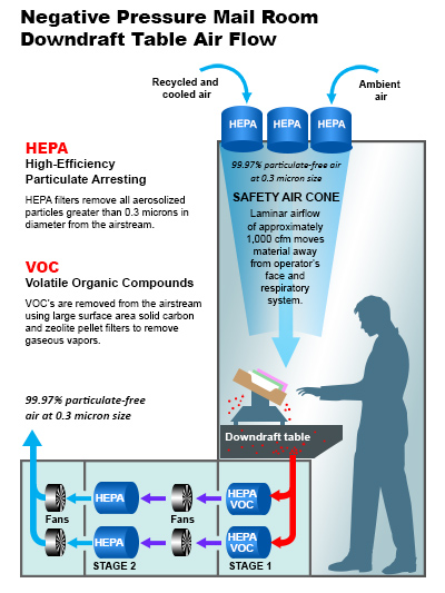
NPRs are typically constructed of light-weight aluminum extrusions and transparent high-strength polycarbonate plastic (Figure 1). Transparency minimizes claustrophobia for workers inside the room and allows visual surveillance of operations from outside. The rooms operate slightly below ambient atmospheric pressure. Incoming and exhaust air are both filtered through high-efficiency HEPA filters, and access is often via air-lock doors—creating an environment similar to an electronic or pharmaceutical clean room. Workers with allergies often find that working in the rooms greatly relieves breathing problems.
Downdraft Strategy
Fresh air is injected into the room from roof-mounted fixtures, creating downdraft conditions within the room (Figure 2). The source may be either ambient air or recycled NPR air that has been thoroughly filtered and cooled. Depending on room size, multiple filtered downdraft air injection vents are installed. Air handlers with HEPA discharge filters remove air from the room. A typical system completely changes the air once every minute.
For comparison, United States OSHA standards for smoking lounges require only 60 CFM per person—a rate nearly ten times less than an NPR.
Air Handling & Filtration
The NPR’s environmental control system utilizes proven HEPA filtration technology for particulate control and carbon/zeolite filtration for chemical gas control. The HEPA filters employed have an efficiency of 99.97% or better for particles > 0.3 µm (a single anthrax spore is ~1.0–1.5 µm in diameter).
It is generally possible to couple the exterior air handlers discharging air from the NPR with the D1000 downdraft tables so that each exhaust filter ensemble contains a foam large-debris prefilter, two HEPA elements in series, and an activated carbon/zeolite filter (Figure 3).

Air is filtered as it enters from the ceiling and then filtered twice more as it leaves the room. The system is deliberately redundant to provide maximum safety to employees both inside and outside the room. In practice, filtered air discharged from the room is so clean that customers have reported noticeable particulate reductions in surrounding office areas after installing an NPR.
Trailer Installations
If there is no space for the negative pressure room inside the building, the fully-functioning NPR can be installed in a trailer, providing mobility for organizations with multiple locations.

Contact
For further information on a negative pressure room for your application, contact us at info@resrchintl.com or 1-360-805-4930.
QuikTest Bioscreen
Operational Details
Principle
The product works primarily by using PurpleHaze™ Technology to identify protein, which is found in all living material. All biowarfare agents, including anthrax and ricin, contain protein. Many harmless substances often mistaken to be potential bioterror agents, such as powdered sugar, drywall dust, cornstarch, and many cosmetics, do not contain protein. QuikTest™ also includes a pH test that provides additional information about the sample, as harmful pathogens and toxins tend to be pH neutral.
Method
The protocol is fast and easy to perform. Samples of the suspicious powder are collected using two chemically treated swabs—one for a protein test and one to measure pH levels—and placed within color-coded test tubes. Each test produces a color change in the solution within five minutes if protein is present or if the sample is acidic or basic.
Reading QuikTest Bioscreen Results
Interpreting test results is simple. Within five minutes, one of three results will display, enabling first responders to determine whether a substance represents a potential threat that requires further laboratory testing.
| Protein Test | pH Test | Conclusion |
|---|---|---|
| Purple: Protein present |
Pale yellow: pH neutral
Red: Acidic
Blue: Basic
|
Further testing is required. |
| No change in color and positive control is purple (test valid) | Pale yellow: pH neutral |
Biological threat unlikely. |
| No change in color and positive control is purple (test valid) |
Red: Acidic
Blue: Basic
|
Biological threat very unlikely. |
RSN 5000
Operational Details
Overview
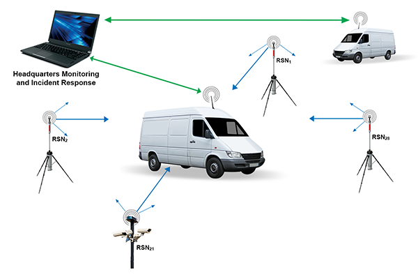
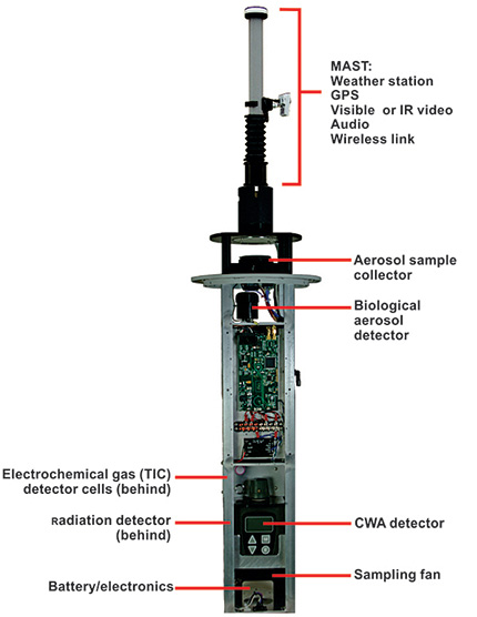
Research International’s Remote Sensor Node is a portable CBRN monitoring device suitable for the detection of toxic gases, aerosolized biological agents, and nuclear materials. Some sensors are mounted within its tough cylindrical aluminum shell of 20 cm diameter and 1 meter height, while other sensors, such as video or thermal IR cameras, can be connected to the node via wireless. A built-in tripod is used to position the unit or alternatively, it may be secured to an adjacent structure using locking rings built into the exterior surface. Anti-theft features similar to those used for automobiles have been incorporated due to their portability. Data gathered by a unit can be wirelessly transmitted to a remote local receiver positioned up to 2 km away. Collected data from multiple nodes may be transferred to a headquarters location 50–70 km distant using commercial RF digital transceivers.
Airflow & Sampling
Air is drawn into the unit through a top cap at the rate of 200 liters/minute and discharged through a perforated cylindrical exhaust section near the unit’s base. The unit is modular in design, and depending on customer preferences, sampled air can be examined for various types of threats:
- Toxic gases can be detected by one or more of four state-of-the-art methods;
- Bioaerosols can be detected by an ultraviolet fluorescence-based biodetector designed to recognize suspicious changes in bioaerosol concentrations; and
- Radiation can be detected by a sensitive gamma ray radiation detector capable of evaluating suspicious changes in background radiation levels.
Automatic Secondary Sampling
If user-adjustable alarm levels are exceeded, a secondary sampling circuit can be automatically activated that collects a permanent aerosol particle sample onto a special high-efficiency filter element. The materials collected on this filter can then be examined using either rapid response portable or laboratory-grade biological, chemical or radiological assay protocols.
Mounting & Internal Components

Portable Weather Station
A portable weather station is available that can be rapidly mounted to the unit and deployed to a height of 3 meters. If a toxic incident is encountered, the weather station provides invaluable information on wind speed and direction as well as GPS location, temperature and relative humidity. This information is needed to predict how the toxic material will disperse in the atmosphere and if crowds or population need to be moved to put them out of harms’ way. Detection of a toxic incident is only the first step in minimizing its impact.
Cameras & Remote Gas Detector
A high resolution video or thermal IR camera may also be associated with the Remote Sensor Node, either being physically mounted to it or placed at a location with good visibility and electronically connected to it by a wireless link. This optional feature is highly recommended as it can be used to monitor a large area for suspicious individuals and can be a deterrent for a wide range of terrorist activities. An area-monitoring gas detector is also available that can be remotely located and connected by wireless link.
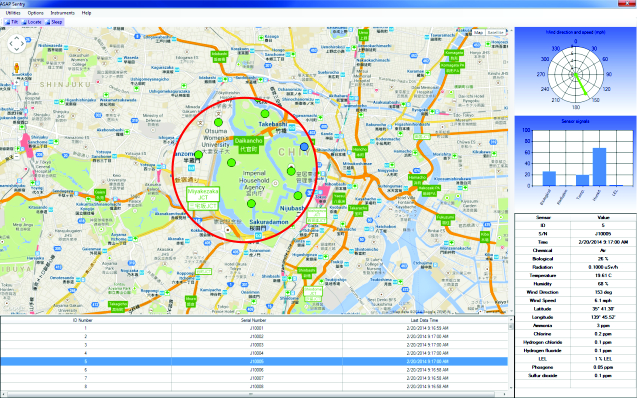
ASAP Sentry™ Software
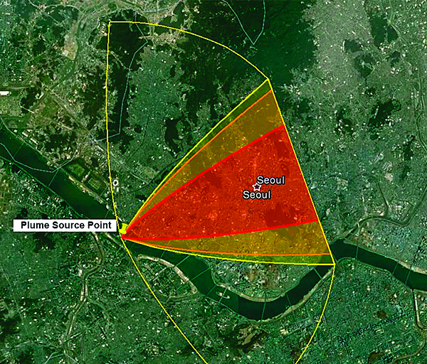
ASAP Sentry™ software is available for integrating the data from multiple Remote Sensor Nodes onto maps of the local area and for predicting toxic plume concentrations and movement based on weather data provided by the portable weather station or by local meteorological stations. These models have been developed by the U.S. government for use by its municipalities.
Robotic Deployment
The unit may also be mounted to a robot for semi-automated deployment. This allows the sensor module to be rapidly moved from place to place. If a toxic event occurs, one robotic detection unit is capable of creating a detailed picture of the toxic plume’s concentration and movement by being positioned for short periods of time at a number of points within the plume’s downwind profile. This can create a rich actionable database not possible with fixed location devices. The robotic device is capable of operation in areas far too toxic or with radiation levels too high to be tolerated by emergency personnel.
Mobile Systems

Research International can also furnish complete turn-key systems for use with vehicles. These systems can be designed to function as local area network monitoring points or mobile sensor platforms, or both. In a typical case, a van will be equipped with built-in desks, storage areas for sensors and protective suits, auxiliary generator and power points, external antenna mounts, air conditioning, etc. If the van is to be used in hostile environments, both the front driving cab and rear work areas can be hermetically sealed to protect drivers and other personnel from exposure to toxic materials surrounding the vehicle.
SASS 2300
Operational Details
Overview
The SASS 2300 collects both particulates and water-soluble chemical vapors from the air. These materials are extracted from the sampled air and trapped in a small volume of liquid that can be removed at any time for analysis. Distilled water is typically the sample liquid of choice and no additives or surfactants are required for high efficiency. Trace aerosol concentrations can be amplified by extending the sampling time to hours or days.
Air is drawn in through a threaded adapter on the unit's exterior. This adapter allows the mounting of your own accessories such as flexible intake tubes, filters and nozzles. A built-in peristaltic pump can transfer liquid samples to an external analyzer for immediate analysis, or to a sample vial filling station mounted on the back of the unit. This filling station is convenient for dispensing all or a part of the liquid sample into a dropper bottle of the type used with lateral flow bioassay tickets.

Fluid Control Subsystem
The particle extraction process involves intimate mixing of incoming air with re-circulating sample water. To prevent evaporation, liquid volume is monitored with a proprietary sensor attached to the water feedback tube. When the sample water inventory falls below a preset level, a microprocessor-controlled peristaltic pump meters a small amount of clean water into the re-circulation loop from an onboard water reservoir to bring the level back to set point. Water inventories can be maintained within a range of about 4 cc to 5 cc with an accuracy of a few tenths of a cc for periods of hours to days (U.S. Patent 6,532,835). Since the re-circulation loop does not use a mechanical pump, power consumption is minimized, delicate organisms are not damaged, and cleaning is simplified.
Samples may be removed at any time using an onboard peristaltic pump. When the unit is operated manually, air flow is stopped during the sample transfer process to allow fluid films to collect as a pool in the bottom of the unit. If the unit is being operated remotely via the serial digital link, air sampling may continue during the sample transfer process. The user can in either case elect to discharge the sample to an onboard sample vial or to a discharge spigot at the rear of the instrument.
The distilled water used by the SASS for sample collection is not generally compatible with analytical procedures used to identify any captured biologicals; most require some buffer such as phosphate-buffered saline. Sample vials for the SASS are provided with a lyophilized buffer that reconstitutes when the sample is pumped in to provide a liquid ready for direct application to lateral flow immunoassays such as the DoD Hand-held Assays (HHAs) or equivalent. Please see our Application Note, “Suitability of SASS 2300 Sample Vials and SASS 3010 Sample Vials for use with Hand-Held Assays,” for description of our test procedure.
Water Inventory & Collection Performance
Aerosol collection characteristics are similar to those of the SASS 2000, but with significant improvements in particle retention over long collection periods. Figure 2 shows the effect of water inventory on the concentration and total number of 1 micron particles in the water phase. From this Figure it can be seen that about 5 cc of water provides optimum performance. The effect of fluid charge is modest as long as very lean, low water charges are avoided.

External Testing & Performance History
The similar SASS 2000 system has been tested at a number of facilities including Dugway Proving Grounds, Aberdeen Proving Grounds, Lawrence Livermore National Laboratory, Battelle Columbus, and the U.S. Naval Research Laboratory (NRL). A test of nine 'personal' sampler designs was conducted at Dugway Proving grounds in April 1997 against airborne Bacillus globigii in a controlled atmosphere chamber. In these tests, the number median aerodynamic spore diameter was 0.9 microns while the mass median diameter was 2.9 microns. At that time, Research International's prototype system tied with two cyclone-based devices for highest concentration factor versus time.
A second set of tests was run at BIO911 in December 1997 in which 11 different samplers were examined. In the period between the two test series, Research International made several improvements to the design that reduced water inventory and made the interior less likely to trap particles. In these tests, the SASS 2000 came in second, performing slightly lower in overall performance than the front-runner, but both it and the first-place system were substantially better than other systems tested. Its favorable performance is particularly notable since the number one system weighed four times as much and consumed 42 times more electric power.
Detailed examinations of SASS 2000 capture efficiency have been performed by Lawrence Livermore Laboratory and Battelle Columbus over the past five years. A compilation of these test results, plotted as capture efficiency versus particle size, is provided in Figure 3. Finally, in portable air sampler tests performed by Battelle Columbus in 2004, no other portable unit was found to be more efficient that the SASS 2000 series.
Collection Efficiency

Software Interface
The SASS 2300 air sampler is microcontroller-based and can function as a stand-alone unit or connected to other sampling, detection or communication systems via RS-232 or wireless link. Purpose-designed software allows for streamlined integration with Research International's RAPTOR and BioHawk biodetectors. The extensive use of microcontroller-based circuits allows overall system operating characteristics to be easily tailored to customer requirements. Reprogramming of sampler operation may be performed at any time over the RS-232 link without having to disassemble the unit.
Customizable Firmware
Users can modify to their liking how the SASS 2300 collects and processes samples using the PC-based software supplied with the system. User-defined protocols can be stored in a PC and the sampler operated from that PC or the protocols can be downloaded to the 2300’s memory. The 2300 will then follow the downloaded instruction set automatically each time it is turned on, even if not connected to a PC.
Sampling Protocols
Parameters are set on the Automatic Mode screen with radio buttons and text boxes as shown in Figure 4. For example, selecting Fan off while pump on will cause the fan to turn off while liquid is being pumped out of the cyclone. If you instead choose Fan on while pump on, the fan will continue to run while the cyclone is being pumped out.

In the upper right hand corner of the Automatic Mode screen is the Delay Before Starting First Cycle text box. A value placed in this box will cause the air sampler to pause before starting the first sampling cycle. This is useful for example if you have stirred up dust during set-up and want the dust to settle before sampling starts. Other text boxes allow you to set (1) how long the fan is on; (2) the amount of time the sample discharge pump is on; (3) the amount of pause time there is between samples; (4) and the number of sampling cycles.
The Cleaning group of controls shown in the bottom of Figure 4 allows the user to run an automatic cleaning protocol at the end of each fan/pump cycle. This is a procedure wherein the sampler is repeatedly flooded with excess fluid and the fan used to circulate this fluid before it is pumped out, thereby flushing contaminants collected during the previous sampling cycle. If no cleaning cycle is needed, simply enter ‘0’ in the Number of cleaning cycles box.
The Cleaning Routine Settings group allows you to set the parameters for this routine. The Cleaning initial fill time allows the user to set the amount of time that the cyclone is filled with fluid. This fill time can be set in tenths of seconds and occurs immediately upon the fan starting. The Cleaning fan run time and the Cleaning pump run time allow the user to set the fan and pump time for the cleaning routine. The Cleaning number of cycles allows the user to repeat the fan/pump cycle a number of times. Typical values for a cleaning protocol are shown in the Figure.
Expert Users
For users who need even more control over the SASS 2300 or need to integrate it into a proprietary system, the Operating Manual provides the user with a set of over 60 ASCII commands that can be sent over the serial data link to either control or interrogate the sampler.
Main Window for Remote PC Operation
If the SASS 2300 is being operated remotely from a PC by wire or wireless connection, the main program window in Figure 5 continuously shows key operating parameters associated with the sampler. A large graph displays the liquid sample volume circulating in the cyclone. The vertical labels on the left side of the graph represent the raw counts from a liquid level detector inside the SASS 2300 while the vertical labels on the right side represent the corresponding milliliters of liquid circulating in the cyclone. The signal from the liquid level detector is displayed in red and normally oscillates about the set point that is represented by a blue horizontal line.

The upper left of the main window shows the Set Point information. The set point is the desired operating volume for the cyclone that the microcontroller-driven electronics in the SASS 2300 maintains while the fan is running, by adding make up fluid as it evaporates or is pumped out.
To the right of the Set Point group in Figure 5 is the Detected Value group of controls. These controls display the reading from the internal liquid level sensor that is used to maintain the liquid volume in the cyclone. This is the value plotted by a red line on the graph.
The Status group in the upper right of Figure 5 shows several system operating parameters. The real-time internal electronics temperature is displayed in the Temp field, in degrees Celsius. The temperature sensor that generates this reading is located on the SASS 2300’s internal PC board. The operating voltage is displayed in the Volts field. The Filling field displays the status of the pump that is used to fill the cyclone with makeup fluid when the fan is running. This pump turns on momentarily for a few seconds at a time to assure that the proper liquid level is maintained in the cyclone. When this pump is off, the Filling field will display the word OFF with a white background. When the pump is on it will display the word ON with a bright green background. The Batt field displays the percentage of battery life remaining. The Liters field displays the number of liters of air that have been sampled since the fan was last turned on. If you are running in Automatic Mode (Figure 4) this field will display the cumulative liters of air sampled since these operations were started.
SASS 3010
Operational Details
Using the SASS 3010
Operation of the SASS 3010 is straightforward. The extractor’s cover is first removed and the filter to be extracted is seated in the extractor cover. The cover is then re-attached and 6 cc of extracting buffer is injected from a dropper bottle vial (Part Number 1760-0006-17). The empty vial is then placed in a sample collection station located in the extractor base (This dual-use vial is used to store extracted sample fluid on completion of the extraction protocol).
In the next step, particulates are dislodged from the filter fiber matrix using acoustic energy, a process that takes about 15 seconds. After this has been done, the liquid sample is transferred to the sample vial by manually pressing the extraction pump plunger shown projecting from the top of the extractor in Figure 1. The extractor cap is then removed and the extracted filter assembly discarded. Overall time to process a filter is about 1 minute; if the extractor’s interior needs to be washed before another filter is inserted, total time is still less than 2 minutes.
No external power is used — two “D” batteries power the sonication step. The batteries can be replaced with no tools by removing 4 finger-nuts on the device’s bottom surface. Due to the short sonication time, a long battery life can be expected.
Extraction Efficiency
Extraction efficiencies are typically in the range of 60 to 80%. To test extraction efficiency, a SASS 3000 and several electret filters were used to collect airborne fluorescent polystyrene beads of 1.8 microns diameter. Each filter was operated for a period of 10 minutes. After the collection phase was completed, the filters were mounted in a SASS 3010 and captured beads transferred to 5 ml of extraction buffer using the protocol outlined below. Extraction efficiencies were then determined using fluorometric assay methods.
It was found that an average recovery of 77% was achieved. A second extraction with an additional 5 ml of extraction fluid resulted in recovery of another 17% of the embedded beads, while two more 5 ml extractions resulted in small 4.5% and 1.5% additions to the total number of beads recovered, respectively.
In a second test series designed to study the effect of particle size on extraction efficiency, fluorescent polystyrene beads of 0.9 to 15.0 microns diameter were spotted uniformly over either the filter’s inlet (air-side) or outlet (fan-side) face from water-based particle suspensions: Each fluid spot had a volume of 10 µl. For inlet-side spotting, a dilute surfactant solution was used: dilute surfactant assists in wicking injected fluid and suspended particles deep into the hydrophobic filter matrix. For fan-side spotting, particle suspensions in distilled water were used. Distilled water results in poor penetration of the particles and provides a worst-case scenario of particle position within the filter. That is, during extraction the particles must travel through the filter’s entire vertical cross-section.

After the filters had been allowed to air dry, each was extracted with 6 ml of Research International’s extraction solution (Part Number 1760-0006-17). Recovery percentages are shown in Figure 1 for the air-side and fan-side spotting tests, and for the previously described aerosol loading test. From this Figure it can be seen that extraction efficiency for particles lodged on the air side of the filter shows no apparent dependence on particle size. For particles deposited on the fan side of the filter, there is a noticeable improvement in extraction efficiency as particle size increases, until the difference in extraction efficiency becomes insignificant between inlet- and outlet-side deposition, for particles larger than about 10 microns. Note that the aerosol extraction test results with 1.8 micron diameter particles are very similar to results when the particles were spotted onto the filter’s air-side from a surfactant solution.
In a third test series, extraction efficiency was determined as a function of extraction fluid volume. For this purpose, 1.8 micron fluorescent polystyrene beads were embedded in the filters by spotting dilute surfactant solutions containing the particles onto the filter’s air-side face, as described previously. Results are shown in Figure 2. These tests indicate that overall collection efficiency is maximized if 4 ml or more of extraction fluid is used.

Taken together, this data implies that the 3010 extractor can be expected to recover about 60% to 80% of the aerosol particles captured by the electret filters used in the SASS 3000 and SASS 4000 dry samplers.
Design Elements Supporting High Transfer Efficiency
- An effective extraction fluid;
- The use of sonic vibration to dislodge particles from the fiber matrix; and
- Regulation of flow so that the extraction fluid enters the rear of the filter and exits the air inlet face, where particle concentrations are highest.
Buffer & Assay Compatibility
The extraction buffer used by the SASS is compatible with DoD hand-held assays (HHAs) or other lateral flow immunoassays for identification of extracted biologicals. The sample vial may be used to directly apply the sample to an HHA or it may be used directly with other analytical techniques. Please see our Application Note, “Suitability of SASS 2300 Sample Vials and SASS 3010 Sample Vials for use with Hand-Held Assays,” for a description of the test procedure that verifies this suitability.
SASS 3100
Operational Details
Overview
In a test1 that compared the performance of ten different wet and dry portable sampling systems from different manufacturers at the U.S. Army’s Edgewood CB Center, the SASS 3100 was the top performer (Figure 1).

Ref. 1: Test Report, Technology Evaluation Readiness Evaluation 08-2, CBR Technology Evaluation Branch, Edgewood CB Center, U.S. Army RDECOM, December, 2008.
Disposable Filter Element
The capture element is a 44 mm diameter felt-like polymer disc with an electric field “frozen” into each fiber (electret media). These fields induce a charge in aerosols passing through the filter and provide a capture mechanism much more effective than impaction—up to 50× more efficient than conventional glass or cellulosic filters. The media is stable to 70 °C, is virtually inert, has a 10-year shelf life, and high holding capacity due to a large internal surface-to-volume ratio.

Absolute Capture Rates
Collection efficiency versus particle diameter for polystyrene test beads shows that particles in the 0.3–0.5 µm range are captured with almost 50% efficiency; 1.0 µm and larger are captured at 80%+ (Figure 3).

Effect of Airflow on Collection Efficiency
Across the suggested 50–300 L/min sampling range, collection efficiency changes modestly (Figure 4). At 120 LPM, efficiency is ~92% for 0.5–5.0 µm particles. At 360 LPM, efficiency is ~78–79% for similar-size particles—but the total capture rate is higher at the greater flow.

Air velocities at the filter face are relatively low versus sieve impactors (≈3.5 m/s at 300 L/min vs. ~20 m/s typical in ISO 14698-1 impactors), providing gentler capture conditions for delicate microorganisms.
Long-Duration Collection Behavior
Over a 7.5-hour collection (≈140 million particles/cm² deposited, 0.9 µm polystyrene spheres), collection efficiency for 0.5–5.0 µm particles increased by ~20%, with a similar ~20% rise in pressure drop (Figure 5).

The capture disc can be processed in the SASS 3010 Manual Extractor for a liquid sample, or placed directly in a 50 mm petri dish for culture-based assay.
Fan Unit & Noise
A brushless DC motor drives a centrifugal fan (expected life 30–40k hours). Power draw is ~8 W; noise is 45–61 dB(A) at 1 m. Peak acoustic level occurs ≈30° from the exhaust port (Figure 6).
 at 1 m vs circumferential position.")
Electronics
Subsystems are controlled by an embedded microprocessor; operating characteristics such as fan speed and sampling behavior can be adjusted via Windows® software, over RS-232 (USB adapter optional) or optional RF wireless.
Long Battery Operating Times
Compatible with BA-5590/U (primary, ~210 Wh) and UBI-2590 (rechargeable, ~250 Wh). Continuous run times are approximately 21 h and 25 h, respectively; standby (fan off) ~8.75 and 10.4 days. Software displays % capacity and voltage when connected. Universal AC supply supports 82–265 VAC, 47–63 Hz.
Packaging
Electronics and battery are enclosed in a leak-tight extruded aluminum shell; the fan rotor projects from and is protected by the filter-mounting plate. Includes carrying handle and two ¼-20 female bosses (handle and base). Approx. 15 cm W × 17 cm L × 20 cm H; weight 1.8 kg.
Decontamination
Pull-through fan minimizes test-to-test contamination. Unit is designed for wash/spray with 5% bleach or gas-phase microbicide. The rotor housing separates via three finger-tight hold-downs; rotor may be sprayed/dunked in situ. Motor and electronics are sealed; motor/rotor service is straightforward if shaft seal ever needs replacement.
Accessories / Options
Standard DB-9 RS-232 connector; optional military CCSI-style available. RS-232→USB adapter and RF link are offered. Inlet/outlet accept air-tight tube adaptors for routed airflow (e.g., inside a vehicle). Contact us for application-specific fittings.
Customizable Firmware
Create and store protocols on PC, run directly from PC, or download to the 3100 so it auto-runs when powered. Airflow set via slider or counts; set delays, fan-on time, pauses, cycle count, or target total air volume.
Sampling Protocols (Auto Mode)
Auto Mode allows initial delay, per-cycle fan times, pauses, total cycles, and total air volume control. Cleaning routines can flood/circulate/pump to flush contaminants at cycle end.

Expert Users (Serial Commands)
The Operating Manual provides a set of ASCII commands (20+ for SASS 3100) to control or interrogate the sampler over the serial link for integration into proprietary systems.
SASS 4000
Operational Details
What is a Concentrator?
A concentrator processes large volumes of ambient air, continuously transferring particulates from this primary air stream to a much smaller secondary air flow (Figure 1). As a result, the secondary flow can reach aerosol concentrations that are 4 to 15 times higher than present in the incoming air. The concentrator therefore amplifies the ambient aerosol concentration, while retaining most of the particles that were present in the incoming air flow in the secondary flow.

Particles are routed into the secondary flow by forcing primary circuit air to circulate through specially shaped channels where centrifugal force and particle momentum are used to isolate and concentrate the particles. The interior structure has been designed so that the smallest flow cross-section is a channel 0.6 mm wide × 6.35 cm long, providing good resistance to clogging by larger particles. A coarse screened cover with 5.4 mm square openings further restricts the entrance of large debris.
Air Flow Patterns
Air flow patterns are shown schematically in Figure 2. Air flows radially inward into the concentrator through the coarse square-mesh screen. This inward radial flow provides 360° sampling of the surrounding aerosol environment. A quick-release tripod that is standard with the product allows the preconcentrator section to be located from about 0.6 m to 1.43 m above the tripod mounting surface.

The primary fan and a curved air shroud are mounted above the concentrator, channeling exhaust air into a vertical stream away from the input air areas. The secondary concentrate air is available at a hose barb fitting designed nominally for 3.8 cm ID hose. This allows the discharged aerosol concentrate to be delivered, with minimum tubing length, to an assay system or wet collector on the ground under the concentrator. We recommend delivering the aerosol concentrate using a smooth-surfaced tube of not less than 3.5 cm ID and length not to exceed 3 m (2 m is preferable).
Any sudden change in the aerosol concentrate tube’s cross-section is to be avoided to minimize particle loss to the tube wall and excessive pressure drop. Tube bend radii should also be as large as possible to minimize secondary circulation patterns and particle collisions with the tube wall.
Collection Blades
The particulate concentration process is primarily performed within 20 rectangular collection “blades” that slip into radial slots in the main structure (Figure 3). These blades are precisely formed to the desired shape using state-of-the-art CNC machining centers at Research International. This manufacturing method assures that air moves as intended within the interior channels and minimizes particle loss through wall collisions, while also minimizing the overall pressure difference required to push air through the device.

Performance (Concentration Factor vs. Particle Size)
Figure 4 shows typical data for concentration factor as a function of particle size for a primary air flow of about 3000–3600 LPM and a secondary air flow of 300 LPM. This figure is based on tests that used fluorescent polystyrene microspheres (density 1.05 g/cc) and fragments thereof as test particles. Concentration factors were determined from multiple test runs using a Met One 200L laser particle counter.

The figure shows that aerosols of this density and with effective optical diameters in the range of 0.5–1.0 µm were concentrated by a factor of 3× to 4×. Particles in the range of 1.0–2.0 µm were concentrated by a factor of 4× to 5×, while larger respirable particles were concentrated by a factor of about 6×.
Effect of Secondary Airflow
Particle concentrations in the secondary flow can be further enhanced by reducing the secondary airflow, as shown in Figure 5. For example, at a secondary airflow of about 40 LPM, the concentration factor is increased by about 3× relative to operation at 300 LPM. However, the total amount of particulate matter collected begins to fall substantially for secondary airflows below about 200 LPM.

Reduced airflow can be valuable if the detection method requires small amounts of fluid. For example, Research International’s standard air sampler, the SASS 2300, has an airflow of about 300 LPM when connected to the SASS 4000 Concentrator and operates with a water inventory of about 5 ml. The SASS 2400 (“Mini-SASS”), however, has a nominal airflow of 40 LPM and a liquid inventory of only about 1 ml. Hence, the Mini-SASS may show a concentration increase of about 15× for this example case, compared to ~5× for the SASS 2300. However, the total amount of particulates collected within a fixed period by the Mini-SASS may be only ~40% of that collected with the larger wet sampler. The best overall collection strategy depends on the application.